Monday, August 29, 2011

Driveshaft removal

Now for one of the more involved tasks I've yet to tackle - getting the driveshaft out. I am not looking forward to this. Yet another greasy mess!

Sadly, I get a bit impatient on this task and make a couple of dorky mistakes.

First up is detaching the rear end of the driveshaft.


The service manual job for driveshaft removal mentions "bending the locking plates", but I'm not seeing anything like that here. (I do find locking plates later on in the task.) I'm assuming that work was done on this end of the car in the past, and the locking plates never put back on or replaced. Regardless, these six bolts/nuts come loose with a bit of oomph, but not too much.

Sadly, during this process, I find that the car seems to have ended up in gear somehow. It certainly wasn't when it was last pushed into the garage in early 2010 - perhaps when removing the shift column, it was put into gear then. What this means is the driveshaft won't spin freely, and to get all these nuts free (and the nuts on the front end as well), I need to recruit a helpful soul nearby to wander over and depress the clutch pedal while I spin the driveshaft by hand.


One of the things the service manual stresses is making marks on some of these parts, to keep track of how they went together, for balancing purposes. Taking a lead from Thomas, a Swedish ponton owner who sent me links to a bunch of photos he took when removing his driveshaft, I hit the rear piece and the splined area it slides onto with some paint. Sadly, this paint doesn't last in the end, and I may have some balancing issues once the car is back together that need resolving. Mistake #1.


Next up is removing the bolts holding the front end of the driveshaft to the transmission. In this case, it's only three bolts, not six.


And then it's time to disconnect the center bearing bracket from the bottom side of the tunnel area. Three bolts hold this in place, with some protective plates in the mix.


Once the center bracket is loose, I take Thomas' advice and use a flathead screwdriver to spin that bracket around a bit inside the tunnel, which should make getting it out easier.

This is where I realize I've made Mistake #2 - as I had not yet removed the rear-most piece of the driveshaft off the spline. With the whole driveshaft loose, it's a more difficult job to wrestle this piece free from the end of the splined area, and to get it around the flange on the rear axle. But, that's a minor issue, and soon I'm working on getting the whole shaft assembly out. Service manual says to put the splined end into the lower left corner of the tunnel and pull it out that way. This is a bit of a task, wrestling the whole assembly into a position that puts the rear shaft at the proper angle so that it clears the rear axle enough that it can be slid out.

But then, trouble! The car is only so far off the ground on jackstands - and not far enough to allow the driveshaft to clear, without the rear end of the shaft touching the garage floor! Not to worry - the solution is simply to get the floor jack into position and jack the rear end up a few extra inches, and then reach under the rear end of the car (I'm not getting under there!) and pulling on the driveshaft until it comes out of the tunnel enough that the car can be lowered back onto the jackstands. Now I can roll back underneath and guide the driveshaft the rest of the way out.


And out it comes!


The center bearing bracket was rattling loose as I pulled the driveshaft out, and the rubber that fits around the main center bearing, within the bracket, looks pretty rough. Fortunately these rubber pieces are available from a number of sources and aren't terribly expensive. The bearing itself seems to spin alright, so I expect it'll be refurbishable.


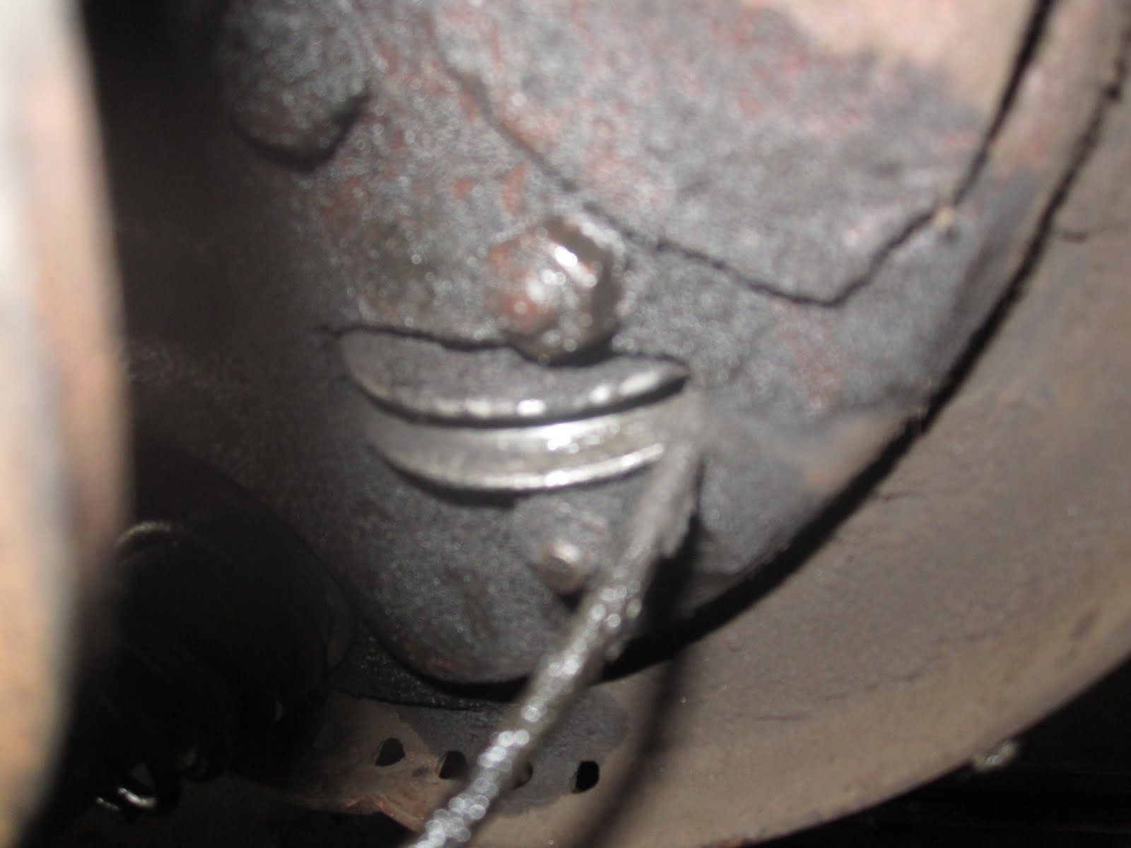
Front end of driveshaft with centering flange.


Now to disconnect the front and rear driveshaft parts. This is where Mistake #3 occurs - I did not properly mark the position of the two pieces relative to each other before taking them apart! But I think I'll be ok on this front, due to the photo above of the whole shaft assembly - as there are small rectangular plates welded onto each shaft piece in various places. I assume these are for balancing, much like the small weights attached to wheel rims. I can use that photo, and the position of those small plates, to connect the two shaft pieces together again in the right way. Phew.

In this area, we have locking plates! There are three of them, one for each pair of bolts/nuts, and the ends of each plate are bent up to rest flush against a flat side of each nut. I have to take a small flathead screwdriver and tap it in sideways on each end of the plate with a hammer - once it's wedged in enough, I can shift 90 degrees and tap the ends of the plates down with the flathead from above the nuts, enough that the nuts can be removed.


Driveshaft pieces detached, with locking plates and nuts scattered. Everything goes into a baggie! The next task will be disassembling the universal joints and doing general cleanup. That can wait until the body is off for some TLC.


Rear brake shoes and rear brake cable removal

Next up on the hit parade - removing the hardware for the rear brake cable (i.e. hand brake).

First order of business is getting the front end of the main brake cable loose. The grippable part inside the passenger compartment, under the dashboard, was removed many moons ago. So the next task is to remove the huge wingnut from the threaded end of the cable.

This turns out to be quite difficult - the nut is on there pretty solid, and will not budge easily. I resort to grabbing a pair of slip joint pliers and unthreading this wing nut a few degrees at a time.


About halfway through, trouble - the cable itself twists out of the channel in the brake lever, allowing the pin pictured to escape. And there's no getting it back into the channel in order to hold the cable steady while putting the needed force on the wingnut. For a bit I thought I was pretty well screwed, and then I ended up clamping a vice grip onto this tab, and letting the end of the vice grip rest against the side of the engine, which gave it the support needed to stay in place while I finished removing the wingnut.

Wingnut conquered! The next task was to get the cable free of the bottom of the brake lever. There's a curved channel for the cable to sit in, but it's held in place underneath by a cotter pin. Said cotter pin basically comes apart in pieces as I attempt to get purchase on it - its in a very annoying, difficult-to-see spot.

Next to come off is the brake lever itself. There's a single bolt holding it to the body. Fortunately, I have the service manual CD available, and I print out the related sections as I tackle each job, so I see the instructions that says "Caution! Left-hand thread!" - which I noticed after a couple of attempts at loosening this bolt the normal direction, heh heh. Once I went righty-tighty, it came loose fairly easily.


That's it for the engine compartment side. Now, the rear end, where I discover just how greasy things can get.


The main rear brake cable hardware, which sits just inside the driveshaft tunnel, above the driveshaft. The cable from the front end is visible coming off the bottom of the photo, heading toward 10 o'clock. It's held to the lever piece (the straighter horizontal bar) by a pin and cotter pin. This cotter pin turns out to be a bear to remove, partly due to the greasy nature of the area and partly due to the close quarters I'm dealing with underneath the jacked-up car. I simply cannot get my arms in good positions to get purchase on this piece. It ends up taking getting my neighbor Frank over, the two of us on the ground on either side, reaching up with one extended arm each, to finally get this pin out. Phew.

The spring comes off easy enough, just a matter of getting a good grip on it. No tools needed on this one.

The rear brake cable is attached to a pair of brackets on either side, not far down from the center portion. Frank, whilst under the car, grabs a wrench and detaches both fairly quickly, so I didn't even get a chance at it. Sneak.

The ends of the rear brake cable pass through cable roller housings, attached to the back side of each rear brake anchor plate. It's difficult to see on this photo, but there are two vertical bolts/nuts - the one obvious one, and then another to the left, with the bolt coming up from beneath. This second bolt is what holds the pulley in place. The roller housing is also held in place by a bolt passing horizontally through the rear axle casing.

In order to get the rear cable ends detached, I have to disassemble the rear brakes. First task is removing the three cotter pins pictured (two on left, one on right).

Once the two larger cotter pins are removed, bolts on the back of the anchor plates can be removed, and the pair of guide pins can be pulled out.

 Another bolt at the bottom, holding the bottom ends of each brake shoe, comes away, and the shoes can be removed along with the brake lever, which the rear brake cable end attaches to.


The remaining task is to remove the two small nuts from the posts holding the pulley housing to the anchor plate.

Success! Another disassembly job complete, mostly. There's a lot of cleaning yet to be done...


Friday, August 5, 2011

Rear bumper finally off, and rear fender removal

So last year, while attempting to remove the rear bumper, I hid a small snag. The bumper has four mount points - two on the main part of the bumper, and one on each of the end pieces. The end pieces appear to have a nut welded onto the back of a plate, that accepts a bolt through the bumper mount - and this nut seemed to broken loose, as the bolt was spinning free.

I had puzzled out that the bumper mount itself was detachable and could pass out through the hole in the fender - and several attempts to detach this mount later, I was still in the same boat.

Sadly, I later discovered that I had been going at it all wrong. The small mount piece also had a nut attached - and all that was required was to get the bolt out. And all this time, I was attempting to loosen the nut! Once this was puzzled out, and with the help of a recently acquired breaker bar and several applications of penetrant over time, the bolt itself came loose fairly quickly, the bumper mount was fee, and the bumper finally removed.


With the bumper off, now I can get to work on removing the fenders themselves. Not a huge task, as it turns out. Here's the left rear fender off.


That fender came off so easily and quickly, I didn't even think about taking photos, so time to break out the camera for the right side.

The rear fenders are held on with a combo of bolts/nuts, bolts, and nuts/posts. Here's the forward end of the wheelwell - three bolts/nuts from the bottom up, and then a couple of bolts that thread into the main body above that.


Up inside, at the top of the forward end, a couple more bolts threading into the body, and one post that comes out with a nut attached. Why this and not just another bolt, I don't yet understand.

There is a pair of bolts/nuts at the rear bottom, easily removed, and the balance of attachments are bolts around the inside of the trunk area, that also hold the clips that hold the wiring harness in place. All of these bolts come away easily (though one did snap off - I'll have to drill the remnant out of the right rear fender at some point).


The last connection to the body is this bar that sits behind the rear wheel, some sort of stabilizer. These bolts/nuts have a lot of road grime/gunk on them - and the nut on the left side ends up getting rounded in my efforts to remove it. I ended up cutting it off once the fender was off.


Before removing the fender, I tackle the bumper mounts. There's three pieces to these - the main piece that mounts to the body with two 17mm bolts, (pictured below the fuel filler tube remnant at the top), the mount that the side end of the bumper mounts to, mounted on the main mount piece with a single bolt (left side), and the mount that the main middle section of the bumper mounts to, which cannot be seen here but is attched to the main mount with a pair of bolts from the back side.


Now that I know the score, these bolts all come away with minimal effort.


All three mounts removed, and posed in basically their usual position.


With the mounts out, the fender itself is removed easily, though I had missed that the vent pipe was still attached to a mount on the underside of the body. A quick cut and no problem.


Time to get the fuel filler area disassembled. Grimy! The filler and breather hoses were cut when the tank was removed back in December '09, so no problems there. The flap covering the gas cap is held on by a pair of bolts passing through the bucket on the left side of this photo, held on with nuts. More grime in this area that I poke at with a screwdriver.


The remnant of the vent pipe basically just... fell off. That was easy.


Once the flap mount nuts are cleaned off a bit and hit with penetrant, the nuts release their hold, and the flap comes off.


Next up is removing the upper and lower sleeves. The upper pops off, just a matter of getting some leverage underneath with a flathead.


Once the upper sleeve is off, the fuel filler tube is then free.


The lower sleeve is not as cooperative - and being fifty-three years old, it's hardened a lot. I end up slicing it off with a box cutter. The remnant of the filler tube on the bottom comes off once I get the hose strap opened up with a pair of pliers.


The inside of the filler tube looks to be in fine shape.


The last thing is to remove the Ulonite reflectors off the fenders.


These reflectors are held on with a nut/washer on the inside of the fender.


Sadly, but not unexpectedly, the post on the back of the reflector is old and weak, and snaps off while attempting to get the nut off. Not a big loss, as both reflectors are so faded, there's barely any red left to them anyhow. I'll be looking for replacements for these in due time. I may just stick a placeholder bolt/nut with some rubber to seal it up in place when the time comes, as it shouldn't be difficult to mount new reflectors after the car is back together. The rubber pieces probably could also be replaced with something more generic, cut to the right shape and fit.