Friday, July 29, 2011

Tail light housing removal

Last year, I started working on removing the tail light hardware. I had done the easy parts - removed the cover, disconnected the wiring, got the guts out. All good up to that point.

The main housing itself attaches to the fender via a post passing through and fastened down inside the fender with a rubber and metal washer and a nut. When attempting to remove this nut from the left tail light housing, the post snapped clean off, flush with the washer. I made some cursory attempts to continue at that point but moved onto to other things.

Today I jumped back on this task. I first tried taking a pick and hammer and tapping at the broken post, hoping to poke it loose - no go. At this point I started working a small flathead under the edge of the seal, thinking perhaps the rubber was sticking to the fender surface. Again, not the case.

In working this flathead in and trying to wiggle things loose in various spots, I saw that the bottom end of the housing was starting to crack a bit. Considering the not-so-sturdy nature of the material its made of, I figured it was doomed, so I wasn't too concerned about getting it out intact. And sure enough, the bottom part of the housing cracked clean off at one point.


I had noticed this whitish-gray material coming out in bits while working the flathead up around the bottom side of the housing - at this point, it's obvious that this stuff covers a fair bit of real estate i the area.

Continuing at it with the flathead, I manage to get the rubber seal loose, enough that except for a small portion that is stuck beneath the housing edge and tears off, the seal comes away. Another piece I'd be looking at replacing anyway, along with the vast majority of rubber on the car.


With the seal removed, there's more of a gap between the edges of the housing and the fender, and I'm able to get more traction with the flathead. Another couple of minutes of wiggling and pushing on all sides, and the housing body comes free.


I'm guessing that it is this corrison or whatever that had the death grip on the housing. 


Quite a bit of it in there. Here's a closer shot of the fender with the crap still present.


And here's the fender after I've spent a few minutes poking at this stuff with a flathead and a pick. Big difference! It was fairly thick on the level area. Big chunks were coming away as I worked at it.


 Now that I know what to expect, I tackle the right tail light housing. Again, the post snaps clean off inside the fender. But there's no corrosion buildup on the right side, and the housing and seal pop right off, hardly any effort!


I'm definitely going to have to replace the left side housing. The right side may be salvagable. It all depends on whether or not I can get the remnants of that post removed without issue. If not, looks like I'll need two housings. :/

Edit: Well, it appears that the post should screw out of the back of the one good housing, if I can get it out. May have to work at it. But, I've worked a nice little deal with a fellow about a half hour away, who has a 190 and a 219 sitting in his back yard - going to get housings, the bulb mount pieces, and covers in very nice condition for a nice price! I may end up buying some other parts from this fellow as well, as it's likely he's going to be having those two cars hauled off sometime soon - will need to get while the getting's still gettable, I suppose.

Monday, July 25, 2011

Brake master cylinder removal

I had planned on tackling the remainder of the brake lines/hoses before giving the master cylinder a shot, but a combination of my attempts at tinkering, plus my having neighbor Frank come by to get some advice from him regarding some of the brake line nuts equalled the pair of us going to town on this part.

Here's the brake master cylinder. It's left of the engine, mounted onto the subframe with a pair of bolts on the forward end, and a bolt/cotter pin holding the rear end of the piston rod.

Forward end of the master cylinder, from below. Six lines enter in on this end - brake fluid reservoir, two to the filter, one for each front wheel, and one line snaking to the rear of the car, where there is a junction to feed fluid to the rear wheels.

Rear of the master cylinder.


The reservoir line nut came away with little fuss, but when I pulled the nut away, it was obvious there was still a lot of brake fluid in the master cylinder.

Fortunately I had not removed any other lines at this point, so I had a cunning plan... to prop my fluid pan up above the brake filter lines, bend the lines over a bit, and then to climb inside the passenger area and slowly depress the brake pedal. Out came the fluid!
A couple of minutes of careful pumping of the brake pedal and the remaining fluid (the vast majority, at least) is out.

Next order of business were the brake fluid lines. These came away with a bit more difficulty.

The three remaining lines - front brake lines and the line to the rear brakes - not so much. One of them did come off early, but the remaining pair simply would not budge. Every tool I tried to gain purchase on these nuts simply slipped. It was at this point I brought Frank over for a consultation, and he suggested simply cutting the lines off at the nuts. Fine by me, I said, as my intention was to go with new lines anyhow during the rebuild process. So we break out a cutting tool. Those lines didn't stand a chance!

Getting that cotter pin out from the back end was a fun task, considering the position and the semi-closed quarters. The piston rod slid right on out once the collar bolt was removed.

Next task, we thought, was to get the main body of the cylinder out. Frank and I double-team the pair of bolts holding the body of the unit to the subframe. These take a few minutes, with Frank below and me above, having to reach over and down into the engine compartment with the car up on jackstands - not the most comfortable position with the edge of the body digging into one's chest. But, the bolts/nuts surrendered in time.

At this point we realized our folly. The two brake line nuts from earlier, the ones that we cut the lines off of? The cylinder is not going to fit out of the hole with those nuts and line remnants remaining. So we cut off the remaining bits of line, down to the nuts. Still no go. I'm about certain that we're going to need to remount the pair of bolts/nuts to give the cylinder body enough stability in order to get the brake line nuts off - but no, now that the lines have been trimmed off enough to allow a socket onto the end of the line nuts, the socket gets the grip that I was unable to get before. I hold the cylinder steady within the mounting hole while Frank pops those suckers off pretty quickly and easily. Phew.

And now, the cylinder body passes out of the mounting hole easily, though there's still a little trick to twisting it out. I expect I'll end up tearing this part down and doing a cleanup and rebuild. The boot to the rear of the body looks like it's in good shape and may be reuseable, we'll see.


Saturday, July 23, 2011

Wheels off, front brake lines/hoses removal

Seeing as I have the fuel lines off the car, now the brake line running from the master cylinder to the rear of the car is hanging free. So it's time to properly get the brake fluid drained so I can get that line out without making a total mess.

First thing is to get the wheels off. I had no chocks so a quick run to Wally World and I'm set. Took a little while to lower each corner of the car, loosen up the lug nuts with a breaker bar and then jack it back up so the wheel could be pulled off.

I did try using the original lug wrench that came with the car, but I could not for the life of me get enough purchase with it. The lug nuts on the car look too shiny to be fifty-three years old - I wonder if they weren't replaced with a different size nut at some point.

Front left brake rotor, which slides off with no trouble. Some of the other rotors needed a bit of encouragment from behind with a rubber mallet.

Brake shoes/etc. All of this will come apart and get cleaned up in time.

Here's the right front wishbone and top of the shock area. Filthy! Look at all that accumulated junk around the ends of the bearing pin to the rear of the shot. I spent a good ten minutes just poking at all of this mess with a flathead to break it loose.

In contrast, here's the same area on the left front wheel. Much cleaner.

The wishbones (at least the top ones) look pretty new, as do the shocks. My cousin did tell me he had the shocks redone at one point some years back, I assume the top wishbones were part of that.

Now to start bleeding the brakes. I had a fun time figuring out where the bleeder nuts were. With the help of some of the Pontoneers, I finally puzzled them out. Here's the front one, left side of photo just behind the curve of the main assembly, sticking out a bit;

And the rear bleeder screw. This one sits directly above the axle and the brake fluid line. The rear bleeder screw still had the rubber caps on them; the front nut rubber caps are no doubt long gone.

These screws came loose with a bit of pushing. Oddly enough, only the first one I tackled, the left front, bled out any fluid. The other three, nada. Not surprising, I suppose, given the time since the car was last driven (around five years or so).

Next up is to remove the brake hoses and lines on the front end. Here's where the hose connects to the engine compartment wall...

...and the brake line that comes up from the master cylinder.  Removing these two lines wasn't terribly difficult, it was just a matter of holding onto the hose end with one crescent wrench, and working on the nut on the end of the brake line inside with another wrench.
Trickier is the right side line. This line comes up from the master cylinder, and snakes its way around the front end of the engine compartment, then loops around behind this plate that sits between the engine compartment wall and the exhaust pipes. I assume this is to keep heat off the brake line and hence, the fluid within.

It took a little while to get this nut unthreaded, as I could only get a few degrees of rotation per attempt due to the cramped quarters.

Back to the left front... the brake line pulls away from the hose on the other side. The brake hose bracket goes into a bag (along with the clips that hold the right front brake line to the engine compartment).
With the brake line removed, the hose is free.
And then it's a simple matter of loosening the other end of the hose, and away it comes. All these hoses and brake lines are going to be replaced in the end - not going to take any chances with the brakes!

Wednesday, July 20, 2011

Fuel/brake lines, part 2

Not much to share with this post, other than I have the fuel lines detached!

I had already removed four of the seven mounts, the rearward mounts; these were held on by washers/nuts threaded onto bolts that passed through the floorboard. The three forward mounts, however, were held on by screws, and I chose to be very careful with these, as the screws themselves threaded into hollow areas of the underbody, areas I did not want to have screw remnants bouncing around in later, should I strip the screw heads and have to resort to cutting/drilling them out.

I ended up dousing each screwhead with penetrant at least three or four times over the past few days, and also gave each area a good poking-about with a small flathead screwdriver, just to scrape away the accumulated road goo from the screwheads themselves, and around the edges of the screwheads where they met the mounts. I would also poke said flathead up between the mount and the body and give the mounts a little wiggle on three sides, just to try and loosen things up.

Today I decided to give these screws another shot. Surprisingly, the first one I tried came loose very quickly! Alas, the remaining two gave me some more trouble. A bit more penetrant, a bit more flathead wiggling, and a few light taps on the screws with a hammer, and some two-handed oomph and the last two screws released their death grip.

Now that the fuel lines are out, I just need to get the brake fluid bled out properly so I can tackle the rest of that system, probably starting with the brake line that ran front-to-back parallel with the fuel lines. That brake line is now hanging free and I'd like to get it addressed sooner than later.

Tuesday, July 19, 2011

Accelerator pedal removal

Having successfully navigated a (to me) major project yesterday, getting the shifting/steering out, I'm feeling more confident. Today I'm tackling something far easier, the removal of the accelerator pedal.

First off is the push rod, which attaches to the right end of the control lever, spun when pressing the accelerator pedal. The other end of the push rod attached to the engine - I assume to the carburetors - and since the carbs were removed a good while back, this end of the push rod was already free.

I popped the push rod off a few days ago, and neglected to take any photos at the time. Basically it entailed working the rubber damper ring off from over a button bolt - just took a few minutes of effort but it came off eventually.

Next up is the return spring. I had tried to detach this part prior to tackling the shifting/steering, and found I could not get the top end of the spring out from the return spring lever - the end of the spring was curved too much, I couldn't get a good enough grip on the spring to lift it up and over to sneak the curved end out of the hole.


But now, with the bearing body out of the way, I can easily reach down to the bottom of the spring, and that end comes away far easier.
Next out is the bolt holding the return spring lever to the end of the accelerator pedal.

The next task is to remove a retaining ring on the end of the control lever. This is another one of those parts that requires a tool with a pair of small posts, to insert into the round holes and to open the ring up enough that it can be removed. At this point I figured I would be better off getting my own tool, instead of depending on neighbors being around to loan me theirs, so I cruised by Lowe's while out for lunch and got what I needed.


I found that the retaining ring on the right side of the control lever was in a very odd position - the gap side of it was towards the firewall. How did that ring get put on in that position, I wondered? But now, taking a closer look at the service manual job info, it said to pull the retaining ring off the left side. I'll have to go look at the removed parts and see if, indeed, the ring is in a more easily accessable position on that end of the control shaft, and it needs to be removed anyway. Oddly the removal job info doesn't show a retaining ring on the right end, so I suppose that was an easy mistake to make.

Eventually I did loosen the right-side ring enough that I could slide it around and get a better purchase on it, and it came off with some tugging.
Now that the ring is off, I could then unbolt the right side bearing that the control shaft mounts within, and slide the control shaft out of the left bearing and out of the end of the accelerator panel. The left bearing comes out the same way as the right, just two 10mm bolts to remove.

Accelerator pedal conquered! I'm considering getting the brake and clutch pedals out next, but I need to make sure they can come out at this point, or whether other disassembly is required first.

Monday, July 18, 2011

Shifting/Steering Removal

Saturday afternoon, I saw my ever-helpful neighbor Frank out in the common drive our townhouses share, and asked him to come over and take a look at something real quick.

Two hours later, we've mostly got the steering jacket and related hardware out of the car. Gotta love neighbors!

I'm going to write this post up with photos in the order that they were taken, for the most part - this is not the proper order to remove all of this stuff, as I discovered. :/

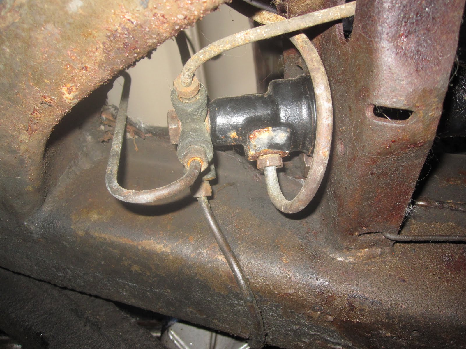
The passenger end of the steering jacket, with the steering column and the guide pin at the end of the shifting tube (the flathead piece on the right) as we're getting started.

The steering column bracket, mounted from below by a pair of posts that insert upwards and held on with a pair of nuts. A thin metal band holds the steering column to the bracket; one end has a cylindrical piece that fits into a notch on the far side of the bracket, and the nearer end has a post with a nut holding the metal band in place. Easy peasy.

First we get the steering coupling loose. One bolt, the one that goes in laterally on the right end of the coupling, I removed some months ago. Yet to come off are some bolts/nuts/cotter pins holding the coupling together.


With the steering coupling loose, the steering tube can be pushed up, bringing the hardware attached to the steering wheel end out with it, including a ring with bearings sealed inside.

Still a bit of wiring that passed through the steering jacket that needs to be pulled out. The cloth wrapping was rotted away in a few spots, so getting the these spots to move through the narrow passage available required a little tugging at times.

Now to start pulling apart the bearing body. First order of business is to detach three ball joints - two on the left, one on the right.

Next to come off is the intermediary lever (I'm looking in the old parts book PDF for names - no idea why this is called this, yet). We remove the bolt/nut holding the back end down on the splined end of the selector lever shaft, and wiggle the intermediary lever off the end. At this point the selector lever and the attached shaft slide right on out as well.


Next off is the lever that fits onto the splined end of the shifting tube. This is attached just like the intermediate lever; bolt/nut holding it onto a splined end.

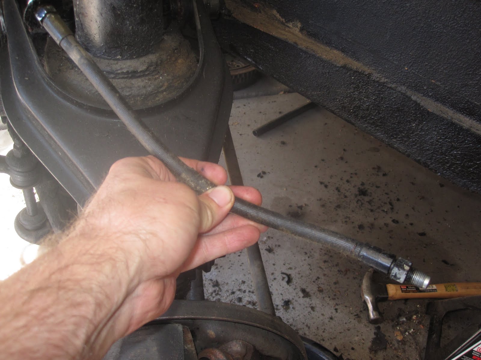
The front end of the steering column is another spline situation. After pushing a large flathead screwdriver into the gap and twisting a little to loosen it up, and a few squirts of penetrant, and quite a few whacks on the sides of the attached piece with a rubber mallet, the coupling part comes away.
With that coupling part free of the steering column, said column slides right on out through the steering jacket from the passenger side. Here we've slid the coupling part back onto the splined end for the time being. Beware Frank's ugly feet.

Next up is unhooking the parking brake. There's a huge winged nut holding the cable end onto the lever - this takes some oomph to move after fifty-three years, but we free up the cable end.

Now we start looking at the inside end.
The steering jacket, besides the mounts shown earlier, is attached to the toeboard with six bolts that thread into cage nuts on the other side of the toeboard. There's a rubber sealing sleeve that sits behind this mounting plate. That part is going to be fun to find for less than an arm and a leg, I fear.

After the six bolts come out, the jacket has nothing holding it up, so it wants to lay down and take a nap. I end up hauling a mostly-useless space heater out, set it on the floorboard, and prop the steering jacket up on it. It's not perfect but it does the job.

Next to come off is a circular clip that has two small holes to use to open it up.

Here, Frank attempts to get the clip off with a pair of small tools. This does not work as planned. And as I have no proper tool to get this piece off, and neither does Frank, we kind of call it a day at this point.

But, not to be defeated, Frank hits up another of our neighbors who, like Jeff Spicoli's dad, "has an aweeesome set of tools" and lays his hands on the necessary tool. He then sneaks into my garage and removes the circular clip while I wasn't looking.


Sunday! Time to get back at it. I don't have Frank around to assist/guide today, so I'm on my own.

First thing I'm going to remove is this small plate on the bearing body. Frank gave it a try yesterday, but obviously just a cursory poke, as I was able to loosen these two screws without too much effort.

The plate has a small gasket on the inside - another fun part to find, joy.

Inside is a piece that holds the selector lever shaft, another splined end situation.

At this point on Sunday afternoon, I was unsure how to proceed - the bearing body would not pass over the end of the shift tube, and I wasn't 100% on the gear inside this small chamber. Fortunately, later that evening, I finally stumbled upon the proper job PDF in the service manual CDs, and could continue the next day. I'm finding that not knowing the terminology of various parts is a handicap as far as sniffing out what job documents are applicable.

Monday afternoon and I'm back at it. First thing to remove is the small bolt holding this piece onto the end of the selector lever. Fortunately this whole area is still quite greased up, and the selector lever slides right on out once the bolt is removed.

Once the selector lever itself is out, the part holding it in pops right out as well.

And now the remainder of the bearing body can slide off the end of the shifting tube.
Next up is to get the shift tube itself removed. First task is to push the guide pin that is at the end of the steering jacket inwards. (We had removed a couple of washer-like pieces holding this end steady on Saturday.) Now that the rest of the hardware is removed, the shifting tube can move inwards, and the guide pin can be removed. In this case, as there is a spring involved, the guide pin shot out right past me.
Now the shifting tube can slide laterally inside the steering jacket, allowing the threaded end that the shifting lever attaches onto to slide through the side of the steering jacket, and the whole shifting tube pulls out via the engine compartment end.

The pesky spring on the passenger end of the shifting tube. This took a little wrestling to get loose. A fair bit of gunk on the end, and this is after I'd removed some of it.

And with the shifting tube out, the steering jacket is free.

Here's the engine compartment, sans shifting/steering hardware;

And the passenger compartment end.
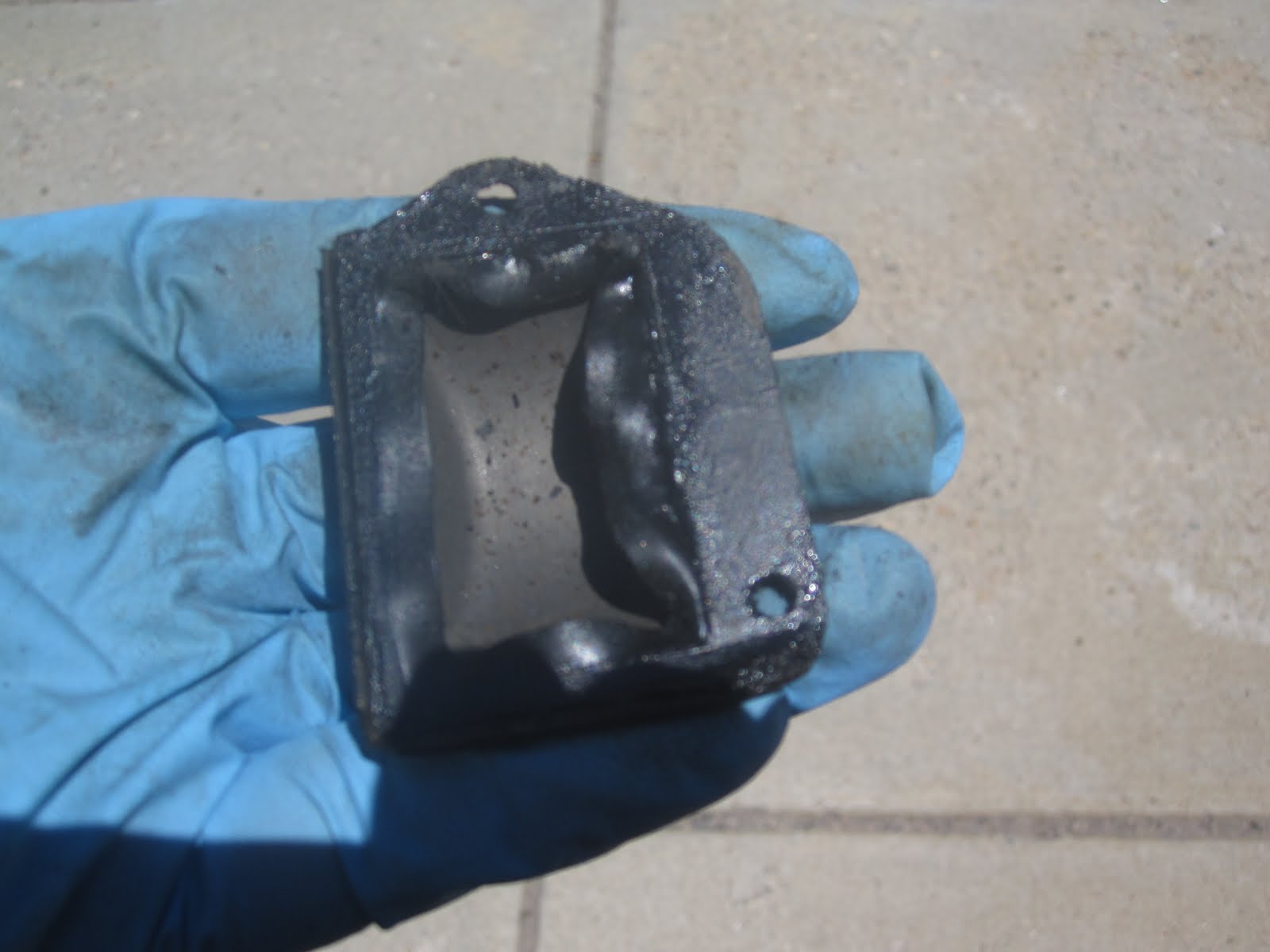
Here's the remains of the rubber seal between the toeboard and the steering jacket mounting plate. Not terribly shot, but still, I'll be replacing it. I wonder if I couldn't simply cut a new piece out of a flat piece of rubber of the same thickness.

The paint on the firewall beneath the steering column has seen better days - very flaky. No matter, it'll all be coming off in the stripping process.